| EENS 2110 |
Mineralogy |
| Tulane University |
Prof. Stephen A. Nelson |
|
Uniaxial Minerals, Uniaxial Indicatrix, Optic Sign, & Ray Path |
|
|
|
|
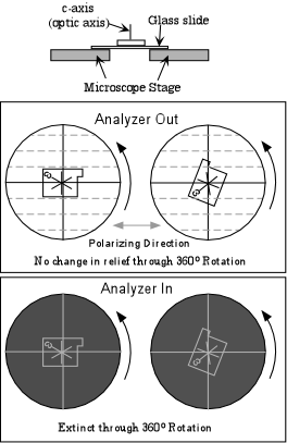
Uniaxial minerals are a class of anisotropic minerals that include all minerals that crystallize in the tetragonal and hexagonal crystal systems. They are called uniaxial because they have a single optic axis. Light traveling along the direction of this single optic axis exhibits the same properties as isotropic materials in the sense that the polarization direction of the light is not changed by passage through the crystal. Similarly, if the optic axis is oriented perpendicular to the microscope stage with the analyzer inserted, the grain will remain extinct throughout a 360o rotation of the stage. The single optic axis is coincident with the c-crystallographic axis in tetragonal and hexagonal minerals. Thus, light traveling parallel to the c-axis will behave as if it were traveling in an isotropic substance because, looking down the c-axis of tetragonal or hexagonal minerals one sees only equal length a-axes, just like in isometric minerals.
|
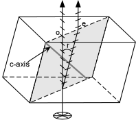
Double Refraction All anisotropic minerals exhibit the phenomenon of double refraction. Only when the birefringence is very high, however, is it apparent to the human eye. Such a case exists for the hexagonal (and therefore uniaxial) mineral calcite. Calcite has rhombohedral cleavage which means it breaks into blocks with parallelogram - shaped faces. If a clear rhombic cleavage block is placed over a point and observed from the top, two images of the point are seen through the calcite crystal. This is known as double refraction. What happens is that when unpolarized light enters the crystal from
below, it is broken into two polarized rays that vibrate perpendicular to
each other within the crystal. |
| One ray, labeled o in the figure shown here, follows Snell's Law, and is called the ordinary ray, or o-ray. It has a vibration direction that is perpendicular to the plane containing the c-axis and the path of the ray. The other ray, labeled e in the figure shown here, does not follow Snell's Law, and is therefore referred to as the extraordinary ray, or e-ray. The e ray is polarized with light vibrating within the plane containing the c-axis and the propagation path of the ray. |  |
Since the angle of incidence of the light is 0o, both rays
should not be refracted when entering the crystal according to Snell's
Law, but the e-ray violates this law because it's angle of refraction is
not 0o, but is r, as shown in the figure. Note that the
vibration directions of the e-ray and the o-ray are perpendicular to each
other. These directions are referred to as the privileged
directions in the crystal.
|
If one separates out the e-ray and the o-ray as shown here, it can be seen that the o-ray has a vibration direction that is perpendicular to the propagation direction. On the other hand, the vibration direction of the e-ray is not perpendicular to the propagation direction. A line drawn that is perpendicular to the vibration direction of the e-ray is called the wave normal direction. It turns out the wave normal direction does obey Snell's Law, as can be seen by examining the diagram of the calcite crystal shown above. In the case shown, the wave normal direction would be parallel to the o-ray propagation direction, which is following Snell's Law. |
 |
|
Uniaxial Indicatrix
Just like in
isotropic minerals, we can construct an indicatrix for uniaxial
minerals. The uniaxial indicatrix is constructed by first orienting
a crystal with its c-axis vertical. Since the c-axis is also the
optic axis in uniaxial crystals, light traveling along the c-axis will
vibrate perpendicular to the c-axis and parallel to the ω
refractive index direction. Light vibrating perpendicular to
the c-axis is associated with the o-ray as discussed above. Thus, if
vectors are drawn with lengths proportional to the refractive index for
light vibrating in that direction, such vectors would define a circle with
radius ω. This circle is referred to as
the circular section of the uniaxial indicatrix. |
|
Light propagating along directions perpendicular to the c-axis or optic axis is broken into two rays that vibrate perpendicular to each other. One of these rays, the e-ray vibrates parallel to the c-axis or optic axis and thus vibrates parallel to the ε refractive index. Thus, a vector with length proportional to the ε refractive index will be larger than or smaller than the vectors drawn perpendicular to the optic axis, and will define one axis of an ellipse. Such an ellipse with the ε direction as one of its axes and the ω direction as its other axis is called the Principal Section of the uniaxial indicatrix.
Light vibrating parallel to any direction associated with a refractive index intermediate between ε and ω will have vector lengths intermediate between those of ε and ω and are referred to as ε' directions. |
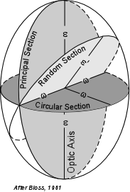 |
| Thus, the uniaxial indicatrix is seen to be an ellipsoid of
revolution. Such an ellipsoid of revolution would be swept out by
rotating the ellipse of the principal section by 180o.
Note that there are an infinite number of principal sections that would
cut the indicatrix vertically.
Light propagating along one of the ε'
directions is broken into two rays, one vibrates parallel to an ε'
direction and the other vibrates parallel to the ω
direction. An ellipse that has an ε'
direction and a ω direction as its axes is
referred to as a random section of the indicatrix. |
| Optic Sign
Recall that uniaxial minerals can be divided into 2 classes based on the optic sign of the mineral. |
|
 |
Application of the Uniaxial Indicatrix The uniaxial indicatrix provides a useful tool for thinking about the
vibration directions of light as it passes through a uniaxial
crystal. Just like crystallographic axes, we can move the indicatrix
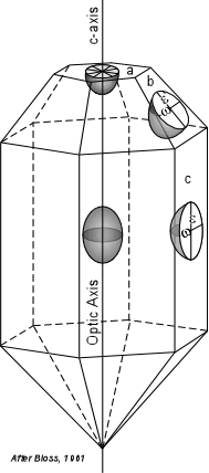
anywhere in a crystal so long it is moved parallel to itself. |
This is shown here for an imaginary tetragonal crystal. In this case the
optic sign of the mineral is positive, and the uniaxial indicatrix is
shown at the center of the crystal.
|
 |
|
Circular Section If a crystal is mounted on the microscope stage with its optic axis
oriented exactly perpendicular to the stage, the circular section of
the indicatrix can be imagined to be on the upper surface of the crystal
such as for the crystal face labeled a in the diagram above.
In this orientation the crystal behaves just like an isotropic
mineral. |
|
 |
| Principal Section
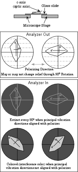
If the mineral grain is oriented such that the optic axis is oriented parallel to the microscope stage, then we can imagine the principal section of the indicatrix as being parallel to the top of the grain such as would be the case for a crystal lying on face c in the diagram above.
In this case, the mineral will show birefringence for most orientations, unless one of the privileged directions in the crystal is lined up with the E-W polarizing direction of the incident light entering from below.
|
|
 |
|
| Random Section
If the mineral grain is oriented such that the optic axis is oriented at an angle to the microscope stage, then we can imagine a random section of the indicatrix as being parallel to the top of the grain such as would be the case for a crystal lying on face b in the crystal diagram above.
In this case, the mineral will also show birefringence for most orientations, unless one of the privileged directions in the crystal is lined up with the E-W polarizing direction of the incident light entering from below But this time, one of the privileged directions corresponds to the ω direction and the other to an ε' direction in the crystal. |
|
 |
|
| Note that by using the Becke Line method and mounting grains of the same
mineral in oils with a variety of refractive indices, we could determine
the w and ε
refractive indices of the mineral. Once these are known we could
determine the optic sign (if ω > ε
the mineral is uniaxial negative or if ε
> ω, the mineral is uniaxial positive), and
the birefringence of the mineral (|ω - ε|).
But, this would be a time consuming operation and would be
difficult.
It would be less difficult in the case where the grain is either elongated in the direction of the c-axis or has a
cleavage parallel to the c-axis (such as {110}, {100}, {010}, or {10 Fortunately, there are other means to determine optic sign and birefringence that are less time consuming. We will learn about these other means in the next lecture. Nevertheless, in lab you will have to determine both refractive indices on a uniaxial mineral as an aid to learning the concepts involved. |
Examples of questions on this material that could be asked on an exam
|